
Everything up to here has produced arch models: a solid model of the jaw at each step, made so that a sheet of plastic can be drawn over it. GuideMia can skip that entirely and build the aligner itself — the shell, terminated at its gingival boundary, with a socket for every attachment — as a file you print directly. No model, no sheet, no trimmer.
The plan does not change. The tooth positions, the staging and the attachments you settled in steps 8 to 10 are the same ones the shells are built from. What changes is the object the generator produces, and the handful of settings that describe it: how thick the shell is, how it terminates between the teeth, and how much clearance your printer needs to make it fit.
Note the word for each thing, because the panel uses both and they are not interchangeable. GuideMia generates arch models and it generates aligners. Direct print describes what you do with the files afterwards.
The last look round before output
Part two of the recorded session opens with the operator doing something worth copying: stepping back through the earlier pages of the workflow and looking at the case one more time.
The row of small icons along the bottom of the Happy Button dock are destinations, not steps. They do not advance anything — they reposition the workflow, opening a page and moving the Happy Button to the step that belongs there, so the wizard and the display stay in agreement. The operator visits the system dashboard, then "Fix models", then "Tooth segmentation", then "Post processing for tooth segmentation", and finally "Model design".
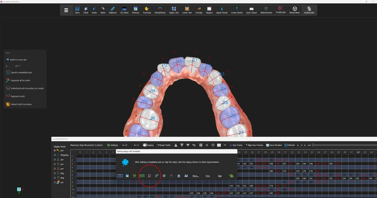 Stepping back to the segmentation page; the Happy Button follows to the step that belongs there.
Nothing is undone by doing this. The models are as they were, the teeth are still segmented, the plan is still staged; you are reading, not editing, and returning to "Model design" puts the Happy Button back on "Add case tag for upper jaw." where you left it.
It is worth the two minutes because this is the last checkpoint. Once the shells are generated and sent to a printer, a boundary that runs through a crown or a tooth that was never properly separated becomes an appliance the patient cannot wear, and the cost of finding it here is a scroll and a glance.
While you are there, turn the analysis overlays off again — "Turn off buccal-libgual movement map" [sic], "Turn off bone density map" and "Turn off Occlusal Distance Map" from the right-click menu — since the pages you have just visited turn some of them back on.
The switch
One checkbox decides everything that follows. On "Aligner or Model Design", tick "With aligner/retainer files":
"This aligner and retainer option tells the system to create aligner or retainer models for direct printing, instead of arch models for thermoforming."
That single tick is the mode. The generate buttons do not change their names or their positions, so a run that produced arch models yesterday and aligners today differs only here — which is why it is worth checking rather than assuming. The setting is stored with the rest of the design configuration and survives between sessions, so a lab that works one way stays configured that way, and an occasional aligner case needs the box ticked deliberately.
Note the option covers retainers as well as aligners; the same pipeline produces both.
You will see two of the options above it go grey the moment you tick it. "No attachments before movements" and "No attachments after movements" [sic] are switched off and held off for the whole run. Their purpose is to save geometry on an arch model where an attachment is not needed yet, and on a printed shell the attachment is a socket rather than a saving. The optimisation does not apply on this path, so GuideMia removes it from your reach.
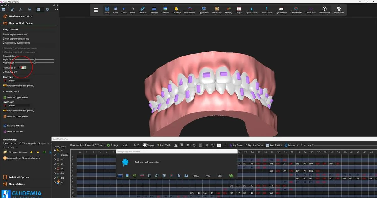 The design page in aligner mode: the aligner/retainer option ticked, the attachment-timing options greyed out.
The four numbers that describe a shell
"Aligner Options" is the section that exists only for this path. Four controls, and a lab will ask about all four.
"Aligner/Retainer Thickness", in millimetres:
"Set the aligner/retainer thickness. The suggested range is from 0.5 to 3.5. Please be advised the final models can have different thickness in different areas."
The number you set is a target rather than a guarantee: as the note says, the finished models can vary in thickness from one area to another, so do not expect a measurement taken at two points on a printed shell to agree.
"Printer Clearance for Aligner Models", in millimetres, is the setting to get right before anything else:
"This parameter compensates the printer pixel size or layer thickness. It needs to be set according to printer specs. Typically this can be half to one pixel size."
This is the offset that makes a printed shell fit. It is a property of your printer, not of the case, and it is set from the printer's specification — half to one of its XY pixel size. If a first batch of printed aligners comes out uniformly too tight or uniformly too loose across every step, this number is the reason.
"Interproximal sharpness", in millimetres, shapes the edge:
"This parameter controls how the aligner models or the trimming paths will conform with the crown boundaries. The bigger the value, the less curved those models are. 3-4mm value would likely make the aligners have flat edges."
Small values follow the gingival scallop between the crowns; large values flatten it out. "Flat Edge" is the override — "This option will force the system to ignore the interproximal sharpness setting so the aligners or trimming paths have flat edges."
"Posterior edge clearance" lifts the edge at the back of the arch: "This will make it easier for the patients to put on and take off the aligners."
The boundary the shell terminates at
A printed aligner ends where the crown ends, and GuideMia calls that line the aligner boundary. Its own explanation of the name is the clearest statement of what it is:
"This function extracts the upper jaw aligner boundary, or, crown boundary. It is called aligner boundary because the individual crown boundaries are merged into a loop. After the boundary is generated, you can adjust it by dragging anywhere on the curve in order to follow the crown boundary better."
The boundary was established back in data preparation, and if it needed correcting this case, it was corrected there. It is worth naming here because it is the line the shell is cut at — anywhere the boundary sits above the true gingival margin, the finished aligner will be short, and anywhere it sits below, the aligner will press on tissue. Manual variants exist for both jaws ("draw the aligner boundary by specifying and connecting points. Go around the model and click on the first point to close the profile.") if a boundary needs redrawing rather than nudging.
Step range and case tag
Set "Step Range" the same way as for arch models. The recorded case runs a short range with "First step only" ticked, which is the verification shortcut described in step 11 and is worth using here more than anywhere else in the guide: print one shell, put it on the model, confirm it fits, and only then commit the range. On a metered licence that test costs nothing.
The case tag works the same way and lands somewhere different. Type the tag first — letters and numbers, no step numbers — then click "Add/Update Case Tag" to place it and click again to finish. GuideMia is explicit that this step is not the same in both modes: "The tag is added in different way for arch models or aligner models." On an arch model the tag sits out on the base, away from the teeth. On an aligner there is no base, so it goes on the shell itself, along the buccal surface where it can be read without taking the aligner out of its bag.
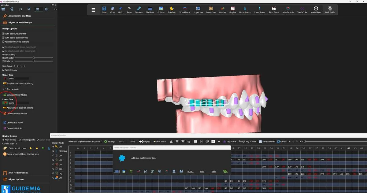 The case tag placed on the lower aligner, on the shell rather than on a base.
Then the upper, with its own field and its own placement.
Generating
"Generate All Models" — the same button, now producing shells:
"All the models within the given step range will be generated for the upper jaw. The function will ask for a file name. Typically you want to create a new folder to hold the files. When you give the file name, do not use aligner numbers."
New folder, no numbers in the name; GuideMia appends the step. As before, the plan is validated first and "OK" on the Plan Validation dialog is enabled only by the acknowledgement tick-box, so read the marked items before you confirm.
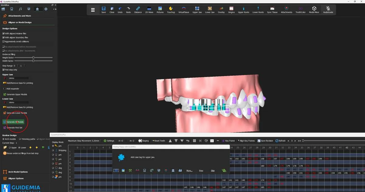 Generating the aligners for the step range.
Several things that a thermoforming run needs are simply absent from this one, and their absence is correct rather than an omission:
- No trimming jig and no trimming path. A printed aligner is already terminated at its boundary. There is nothing to trim, so there is no fixture to hold a model in a trimmer and no path to drive one.
- No virtual soft tissue. An arch model is printed with gingiva so the sheet has something to wrap; a shell stops at the boundary and does not need it.
- No hollowing and no printing base. Both are arch-model economics — resin saved on a solid model, and support for printing it upright. Neither applies to a shell, which is already hollow and already thin.
At an extraction site the handling differs too. GuideMia performs the extraction on the original tissue model at step 0 and restores the tissue for the rest of the run, and the option "Keep space for aligners" — "This option will set the extraction mode to partially remove the crown area." — leaves a pontic-like volume rather than a hole, so the shell has something to close over.
Reviewing the shells
The "Review Design" transport works exactly as it did for arch models: pick the jaw, then walk the set with the next and previous buttons while "Current Step:" tells you where you are.
What the transport shows you depends on what the run generated. The recorded case ticks both "With aligner/retainer files" and "With aligner boundary files", so the boundaries are written alongside the shells and you can choose to view them — select the boundaries and walk the same set to see the edge each shell was cut to, which is the quickest way to check a margin you are unsure about against the curve that produced it.
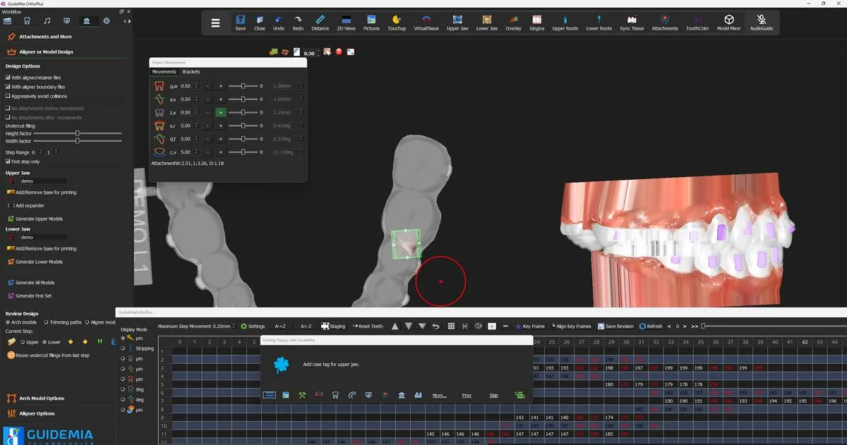 A generated aligner in the working window, with its case tag and an attachment socket selected.
What to look at, in this order:
The sockets. Every attachment on the tooth should have a matching pocket in the shell, with a clean wall around it. A socket is the feature most likely to show a defect, because it is where the shell has the most geometry to follow.
The margin. Turn the model to the occlusal and follow the edge all the way round both sides. It should run parallel to the gingival line at a consistent height, scalloped or flat according to how you set the interproximal sharpness, and it should not dip below the crown anywhere.
The tag. Legible, on the buccal, in the same place on every step.
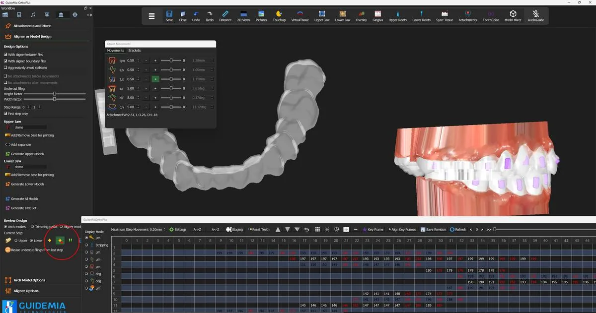 The same aligner from the occlusal, showing the margin all the way round the arch.
Step past the last file in the set and GuideMia says so:
"File not found" — "No more file to edit."
That is the end of the range, not a fault. Click OK, switch jaws, and walk the other side.
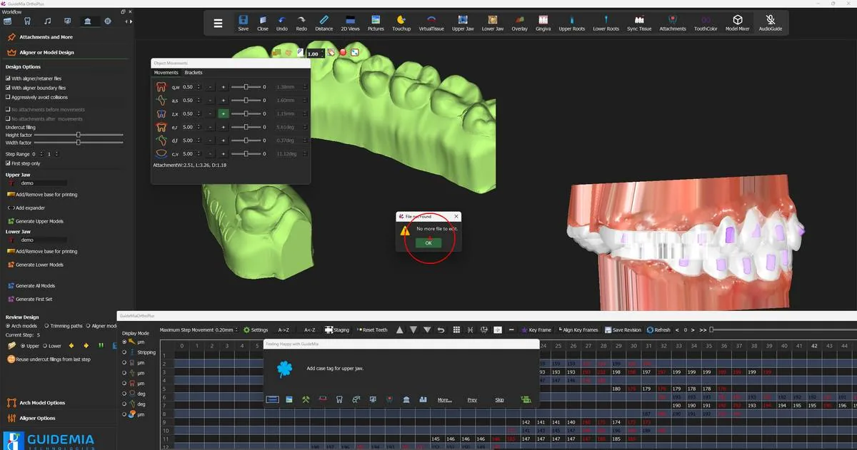 The end of the review set for one jaw.
Where you are now
A folder holds an aligner for every step in the range, for both jaws, each one tagged and numbered, each one carrying the sockets for the attachments on the teeth it covers. Those files go to a printer as they are.
Two matters sit outside this guide and should go to GuideMia rather than be guessed at: resin selection and post-processing, which are a regulatory question and not a software one; and whether your licence covers aligner design for printing, which is an entitlement question — see the licensing guidance.
"Aligner Options", and the controls on the design page that behave differently once "With aligner/retainer files" is ticked:
| Control | What it is for |
|---|---|
| "With aligner/retainer files" | The mode switch: aligners instead of arch models |
| "Aligner/Retainer Thickness" (mm) | Target shell thickness; 0.5–3.5 suggested, and it varies across the shell |
| "Printer Clearance for Aligner Models" (mm) | Set from your printer's spec — half to one pixel size. This is the fit |
| "Interproximal sharpness" (mm) | How closely the edge follows the crown boundaries; 3–4 mm gives flat edges |
| "Flat Edge" | Overrides interproximal sharpness and flattens the edge outright |
| "Posterior edge clearance" (mm) | Lifts the edge at the back of the arch for easier seating and removal |
| "Upper jaw aligner boundary" / "Lower jaw aligner boundary" | Extracts the boundary loop; drag the curve to adjust |
| "Manual upper jaw aligner boundary" / "Manual lower jaw aligner boundary" | Draw the boundary point by point; click the first point to close |
| "Keep space for aligners" | Partial crown removal at an extraction site, so the shell has volume to close over |
| "Aligner models" (Review Design) | Reviews the generated shells; available only in this mode |
| "First step only" | One shell for verification; free on a metered licence |
| "Tag on crown too" | A small aligner number on the first posterior tooth without an attachment |
The arch-model controls stay on the page and stay inert: the fixture choice, "Gingiva margin", "Hollow models" and "Add/Remove base for printing" all belong to the thermoforming path, and a shell run passes them by.