
Two things happen in this step, and although the Happy Button runs them as one continuous sequence they answer different questions.
The crown boundaries answer where the teeth are. GuideMia traces the line where each crown meets the gingiva, and merges those individual loops into one continuous curve per arch. The software calls that merged curve the aligner boundary — the name refers to the merging, not to the individual crowns — and you will see both terms. It is the input tooth segmentation depends on: step 5 does not find the teeth from scratch, it cuts along boundaries that are decided here.
The base models answer what the arch is made of. The scans are open surfaces, and an aligner cannot be formed on an open surface any more than an arch model can be printed from one. Base models are the closed, solid arch models everything downstream is manufactured from — trimmed back to the aligner boundary, extended, and closed underneath.
Extracting the boundaries
The Happy Button reads Crown Boundaries:
Extract and adjust the crown boundaries.
Before pressing it, the operator turns the occlusal distance map off from the model's context menu, so the model is shown in its own colours rather than under a contact-shaded overlay. The display toggles are covered in step 7; the habit is worth adopting now, because every judgement in this step is a judgement about a line on a surface, and a colour map over the surface makes the line harder to read.
Pressing extracts the aligner boundary on both jaws in one go and looks down at the arches from above. What you get is a violet loop running round every crown on both arches.
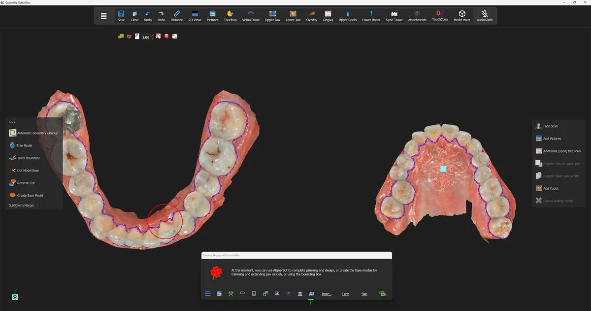 Both arches with the aligner boundary extracted — one continuous loop per jaw, following the gingival margin of every crown.
Check the boundary before you go on, and check the teeth the scan-quality dialog named first. The boundary is dragged anywhere along its length to correct it — you do not have to redraw a segment to move it. Look for the loop running up onto a crown where the gingival margin is indistinct, and for it dropping down into the gingiva where the scan is thin.
What GuideMia wants from the arch curves
The boundary is derived with the help of the arch curves, and this is where the work you put in pays off later. GuideMia's own explanation of what a good arch curve looks like is the most useful passage in the wizard:
Adjust the curves so that they follow the shape of the dental arches. It is suggested to make sure that for each of the teeth, if there are interproximal areas on both mesial and distal side, imagine a line connect the two sides. Make sure the arch curves follow such a line for each of the teeth. This will help segmentation. The curves don't have to pass or be over the teeth, but should follow this direction.
So the curve is not a cosmetic outline of the arch. Through each tooth it should run in the direction of that tooth's own mesial-to-distal line. A curve that sweeps smoothly past a tooth which is itself rotated out of the arch is a curve that will mislead the segmentation.
Three specific cases are worth knowing before you meet them:
- The range bars. Two short horizontal bars sit on each arch curve. They set the range that will be segmented. Move them so they sit close to the last posterior teeth you intend to treat.
- A missing tooth. Drag the curve so that its buccal and lingual sides meet in the middle of the gap. If you do not, GuideMia will treat the gap as tooth area and try to find a crown there.
- A tooth completely out of the arch. Exclude it from the boundary curve altogether and segment it by hand later, rather than distorting the curve to reach it.
Building the base models
The Happy Button now reads Create Base Model, and takes two presses.
At this moment, you can use AlignerBot to complete planning and design, or create the base models by trimming and extending jaw models, or using the bounding box.
This is the second point at which GuideMia offers to finish the case on its own. AlignerBot from here would run the remaining steps — base models, segmentation, planning, staging and design — without stopping. Everything the rest of this guide describes is what it would be doing.
Press, and GuideMia trims the model boundaries back to the extracted aligner boundary and builds the upper base model. The margin box on the tool bar, set to 5.00(mm), is the distance it leaves between the model boundary and the crown boundaries.
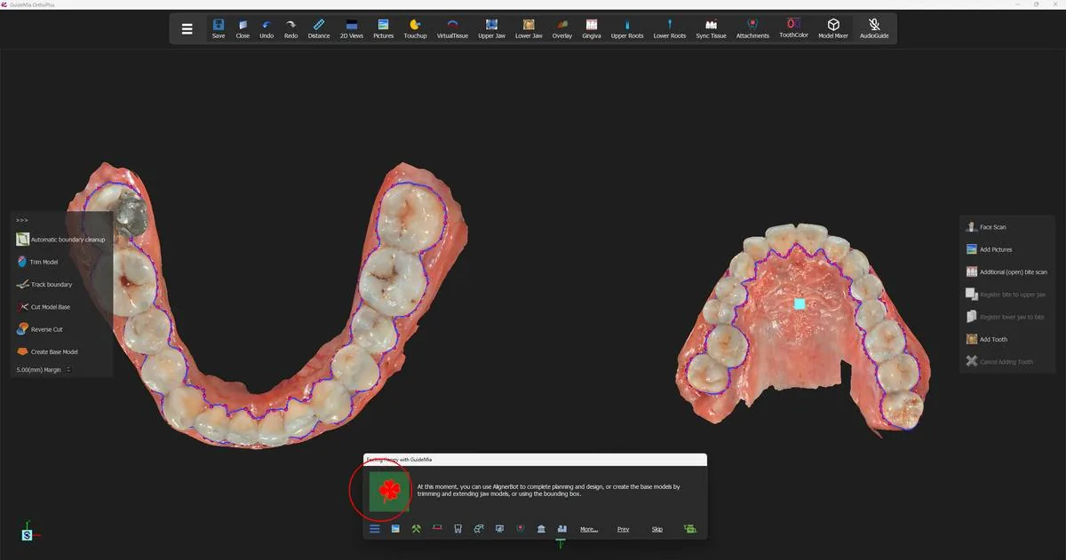 The first press of Create Base Model, with the trimming tools and the margin box on the bar at left.
The automatic trim is honest about its own limits:
The automatic trimming may not generate ideal models. It may have excessive materials if the original scans are not ideal.
If a model comes out with more material than you want, right-click it to make it current and use the trimming tools — "Track boundary" to draw the line and "Cut Model Base" to cut to it — before pressing on.
The grey side
The second press finishes the models, and its instruction carries a warning that you must act on rather than read past:
Click the Happy Button to finish the base models. Before you continue, if any of the models show gray colors on the external side, you can right click on the model and reverse the model direction.
Grey on the outside of a model means the surface is facing inwards — its normals are reversed. GuideMia does not correct this for you, and it is not cosmetic: a model whose outside is its inside cannot be closed into a valid solid, and everything built on that solid inherits the fault.
So before pressing: turn both models and look at them from outside. If either reads grey where it should read like a surface, right-click it and reverse the model direction, and only then press.
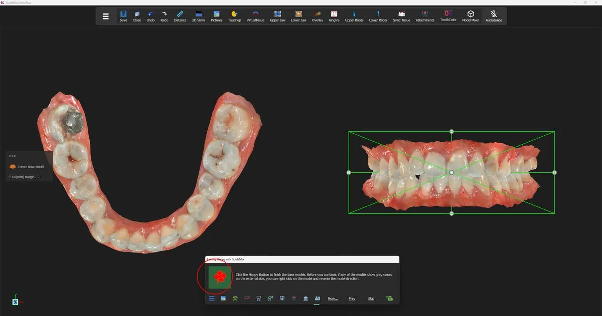 The second press, with the lower base model closed at left and both arches boxed in the assembly window at right.
Pressing finishes the lower base model and moves the workflow on to tooth segmentation.
One thing to file away for later. You are not locked out of this step once you leave it. GuideMia is explicit that you can come back at any point in the workflow — even after treatment planning — regenerate the arch models if they turn out to be too short for aligner manufacturing, and then use Sync Tissue on the toolbar to re-segment the teeth. The tooth setup and movement plans are reapplied to the new models automatically.
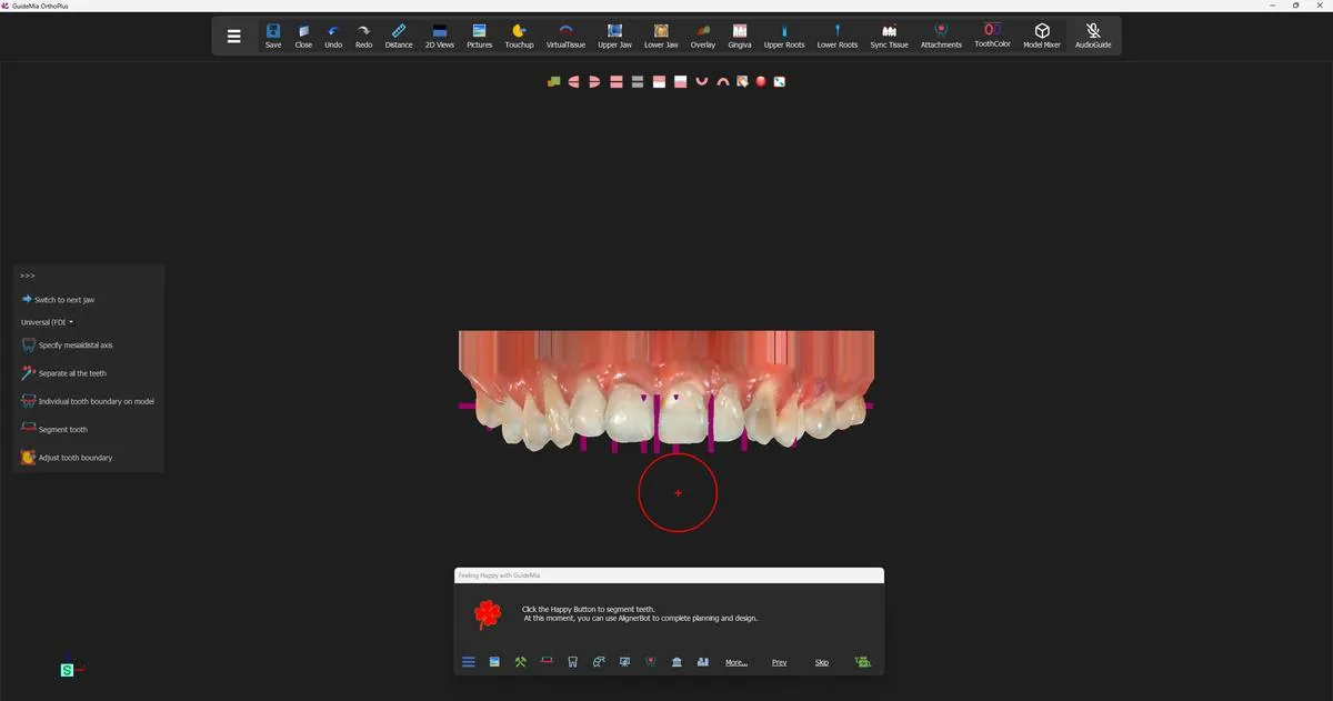 The finished base models, with the workflow now standing on tooth segmentation.
Where you are now
Both arches are closed solid models, trimmed to a boundary that follows the crowns, and each arch carries a continuous aligner boundary and an arch curve that describes the run of its teeth. That is everything tooth segmentation needs as input. It is still one object per arch — the teeth do not exist yet as things you can move. That is the next step.
The "Arch and boundaries" section of the workflow panel's data-preparation page owns the boundary work, and the "Base Model" tools sit on the data processing section beside it:
| Control | What it is for |
|---|---|
| "Show arch lines" | Show and adjust the arch curves the boundary tools work from |
| "Upper jaw aligner boundary" | Extract the upper crown boundary as one merged loop |
| "Lower jaw aligner boundary" | The same for the lower arch |
| "Manual upper jaw aligner boundary" | Draw the upper boundary by hand, point by point, closing on the first point |
| "Manual lower jaw aligner boundary" | The same for the lower arch |
| "Wala ridge" | Mark the Wala ridge on the lower arch |
| "Automatic boundary cleanup" | Tidy the model boundary; needs the crown boundaries to exist first |
| "Create Base Model" | Build the closed arch models on their own, outside the wizard |
| The margin box | Distance from the model boundary to the crown boundaries; 5.00(mm) here |
| "Trim Model" / "Track boundary" / "Cut Model Base" / "Reverse Cut" | Trim a model back by hand before closing it |
Two asymmetries in that list catch people out. The manual upper boundary is drawn in the assembly window on the right; the manual lower boundary is drawn in the working-object window on the left, and if the lower jaw is not showing there you right-click it in the assembly window to make it current first. And the "Create Base Model" button in the panel is not quite the one the Happy Button pressed — the wizard's version uses the extracted crown boundaries to trim the jaw models automatically before closing them, and the panel's version gives you a bounding box to size by hand instead.